
Gamma line calculation via APEX
©️ Copyright 2023 @ Authors
作者:
zhuoyli@outlook.com 📨
日期:2023-07-25
共享协议:本作品采用知识共享署名-非商业性使用-相同方式共享 4.0 国际许可协议进行许可。
快速开始:点击上方的 开始连接 按钮,选择 bohrium-notebook:2023-05-31镜像 和任意配置机型即可开始。
📖 Getting Started Guide
This document can be executed directly on the Bohrium Notebook. To begin, click the Connect button located at the top of the interface, then select the bohrium-notebook:2023-05-31 Image and choose your desired machine configuration to proceed.
The Bohrium notebook demonstrates how to calculate Gamma line (stacking fault energy) with help of APEX. The related computational tasks are submitted to the Bohrium platform, so you need to have a Bohrium account to start the workflow. Then you can monitor the workflow process on the website.
For general introduction and hands-on of APEX, please refer to Hands-on to APEX.
If you have any trouble with the APEX, issues are welcomed in https://github.com/deepmodeling/APEX/
Introduction

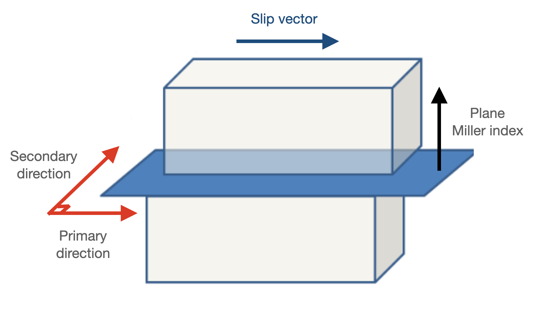
Figure 1. Schematic diagram of Gamma line calculation
The Gamma line (generalized stacking fault energy) function of APEX calculates energy of a series slab structures of specific crystal plane, which displaced in the middle along a slip vector. As illustrated in Figure 2, the slab structrures in APEX are defined by a plane miller index and two orthogonal directions (primary and secondary) on the plane. The slip vector is always along the primary directions with slip length defined by user or default settings. Thus, by indicating plane_miller and the slip_direction (AKA, primary direction), a slip system can be defined.
The parameters related to Gamma line calculation are listed below:
| Key words | Data structure | Default | Description |
|---|---|---|---|
| plane_miller | Sequence[Int] | None | Miller index of the target slab |
| slip_direction | Sequence[Int] | None | Miller index of slip (primary) direction of the slab |
| slip_length | Int|Float; Sequence[Int|Float, Int|Float, Int|Float] | Refer to specific slip system as the table shows above, or 1 if not indicated | Slip length along the primary direction with default unit set by user or default setting. As for format of [x, y, z], the length equals to |
| plane_shift | Int|Float | 0 | Shift of displacement plane with unit of lattice parameter (positive for upwards). This allows creating slip plane within narrowly-spaced planes (see ref). |
| n_steps | Int | 10 | Number of steps to displace slab along the slip vector |
| vacuum_size | Int|Float | 0 | Thickness of vacuum layer added around the slab with unit of Angstrom |
| supercell_size | Sequence[Int, Int, Int] | [1, 1, 5] | Size of generated supper cell based on slab structure |
| add fix | Sequence[Str, Str, Str] | ["true","true","false"] | Whether to add fix position constraint along x, y and z direction during calculation |
Here is an example:
{
    "type":            "gamma",
    "skip":            false,
    "plane_miller":    [0,0,1],
    "slip_direction":  [1,0,0],
    "hcp": {
          "plane_miller":    [0,1,-1,1],
          "slip_direction":  [-2,1,1,0],
        "slip_length":     [1,0,1],
        "plane_shift": 0.25
      },
    "supercell_size":   [1,1,6],
    "vacuum_size": 10,
    "add_fix": ["true","true","false"],
    "n_steps":         10
  }
It should be noted that for various crystal structures, users can further define slip parameters within the respective nested dictionaries, which will be prioritized for adoption. In the previously mentioned example, the slip system configuration within the "hcp" dictionary will be utilized.
Hands-on example
Install APEX
Download APEX packedge via git clone
APEX can be easily installed via pip, as well as other dependencies such as pydflow.
check if apex is installed
Preperation
Here we take an example of APEX workflow based on molecular dynamic simulation tool: LAMMPS, testing Gamma Line of slip along 1/2<> for BCC molybdenum using a DP potential. This process will be running on Bohrium.
Here is a example of local working direction prepared for LAMMPS
global.json contains necessary config for Bohrium (e.g. account infomation; machine type; image address et al.), and should be prepared under current work directory in the first place.
Please replace with your own Borium username, password and program_id via following code:
For most common slip systems in respect to FCC, BCC and HCP crystal structures, slip direction, secondary direction and default fractional slip lengths are already documented and listed below (Users are strongly advised to follow those pre-defined slip system, or may need to double-check the generated slab structure, as unexpected results may occur especially for system like HCP):
FCC
Plane miller index Slip direction Secondary direction Default slip length BCC
Plane miller index Slip direction Secondary direction Default slip length HCP (Bravais lattice)
Plane miller index Slip direction Secondary direction Default slip length
Now let's revise the settings inside param_joint.json to turn on Gamma function:
By this setting, we will be calculating gamma line along on plane as being default to be slip length. You can also specify it inside json.
Submit a joint workflow (relaxation + property-test)
Now we can submit an overall joint workflow to obtain the stacking fault results by:
It may takes a few minutes to submit to Bohrium depending on one's network connection...
Once submitted, we can monitor this workflow on the workflow link appearing above.
When the workflow completed, the work directory, together with results, will be downloaded automatically to current directory:
We can now plot the Gamma line results:


